EQ5 GoTo Mount Modification
This page details the modifications I have made to my Sky-Watcher EQ5 mount, converting it to belt drive with stepper motors, and adding intelligent control with the OnStep project built around an ESP32S microcontroller.

Mount Re-build
Before starting the conversion to belt drive on both axis I spent a weekend stripping the mount down, clearing out the old grease, and regreasing it with lithium grease before reassembling and tuning it for much smoother performance. I followed this excellent guide produced by Astronomy Boy to complete the rebuild.
Belt Drive Modifications
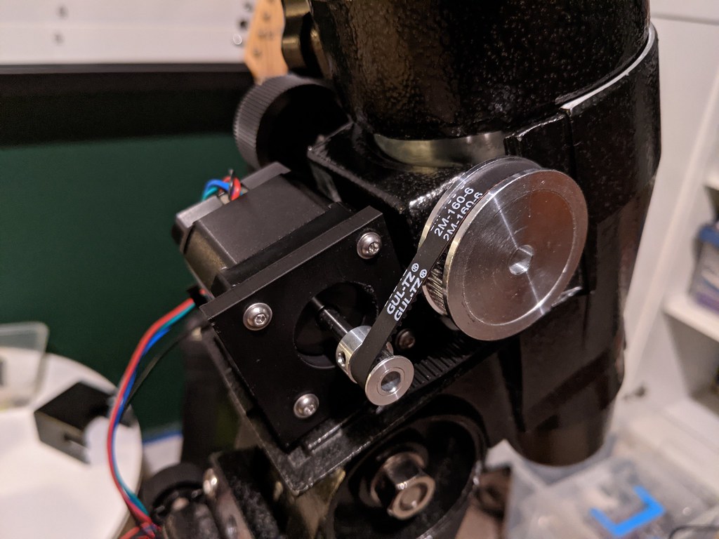
The next stage was to add belt drives to the RA and Dec axis. Although the mount was supplied with a basic clock drive I wanted to replace this with a more powerful stepper motor and belt drive combination that should provide smoother and more accurate tracking. Adding a drive to the Dec axis would allow me to implement a full GoTo system which would be especially beneficial for deep sky imaging.
I found a few forum and blog posts regarding adding belt drives to the EQ5 and using these was able to identify the necassary components and mounts.
The conversion was mostly straight forward. I had to do a bit of trial and error with the belt sizing. One issue I found was that my worm gear shaft, particular on the RA axis, is not very straight which leads to some wobble. I suspect this is a cause of periodic error seen even before I started any of this modification work. I am keeping an eye out on eBay for a spare worm gear and shaft to see if replacing it will solve the issue.

Bill of Materials
| Item | Specification | Quantity |
|---|---|---|
| Stepper Motor | NEMA 17, 400 step, 2A, Bipolar, 0.9deg, 46Ncm (17HM19-2004S1) | 2 |
| Large Drive Pulley | GT2 Drive Pulley, 60 tooth, 6mm Width, 6mm bore | 2 |
| Small Drive Pulley | GT2 Drive Pulley, 15 tooth, 6mm Width, 5mm bore | 2 |
| RA Axis Belt | GT2, 6mm Wide, 79 Teeth, 158mm | 1 |
| Dec Axis Belt | GT2, 6mm Wide, 77 Teeth, 154mm | 1 |
| Motor Screws | Hex Allen Bolts, A2 Stainless, M3x10mm | 8 |
| Motor Washers | Flat Washer, A2 Stainless, M3 | 8 |
| RA Axis Securing Bolt | Hex Allen Bolt, A2 Stainless, M4x40mm | 1 |
| RA Axis Securing Nut | A2 Stainless, M4 | 1 |
| Dec Axis Securing Bolt | Hex Allen Bolt, A2 Stainless, M5x20mm | 1 |
| Dec Axis Securing Nut | A2 Stainless, M5 | 1 |
* Motors would ideally be less than 1A like this.
** Some people in the OnStep group argue that a 60 tooth gear is too big on the EQ5 mount and will cause clashes. An alternative proposal is to use a 48T or 40T pulley on the worm gear shaft to avoid this issue.
*** The nearest standard bore size seems to be 6.35mm which is what I ended up using. Pulleys with 6mm bores are available from China via AliExpress.
3D Printed Motor Mounts
There are multiple possibilities for mounting the motors to the mount, including using brackets or 3D printing mounts.
I went down the route of 3D printing mounts and found this NEMA 17 mount on Thingiverse. I don't have a 3D printer so I used Rennd to print the mounts.
The printed mounts were a good fit, especially the DEC which slotted in perfectly. The RA axis required some modification to reduce the depth of the slot on the underside. I sanded this down with a Dremmel. For both mounts I drilled out the top of the securing hole so that I could insert a securing nut into which the bolt would screw. The mounts have slots to fit an RJ11 socket but unfortunately the stepper motors I had ordered were a little too deep and so prevented me from using this. A stepper motor of <40mm depth would be needed.
Searching on Thingiverse reveals quite a few alternatives, including:
Basic Tracking System
My original plan before coming across the OnStep project was to build my own basic tracking system using an Arduino Nano and a single stepper driver for the RA axis. This would essentially replicate the basic clock drive originally supplied with my mount which has the ability to track and move the RA axis back and forth at a couple of different speeds.
Using the Arduino Nano and a DRV8825 stepper driver this proved relatively straightforward and I quickly had a breadboard prototype which could track at the appropriate rate and move at two other speeds in either direction (see the code on Github). I added a HC-05 bluetooth module and used the MIT App Inventor to make a basic hand controller for my Android phone. This was a lot of fun and very easy to accomplish.


OnStep GoTo System
It was at this point that I came across the OnStep project and quickly focused my attention on what is a much more capable open source mount control system...
OnStep is a complete tracking and goto system designed to work with several different microcontrollers and stepper motor drivers. I had an ESP32 microcontroller available and based on its particular pin-out I chose to base my system on the MaxESP Version 2 which is described in detail in the OnStep Wiki. This has been replaced by a more advanced Version 3 but this requires more I/O than I had available. At this stage I only really need the ability to control the RA and DEc axis, and communicate with the system, so was able to put together a fairly streamlined version on a breadboard to test everything out.

Bill of Materials
| Item | Specification | Quantity | Cost |
|---|---|---|---|
| Microcontroller | ESP32 30-pin DOIT Layout | 1 | £7.80 |
| Wifi Module | WeMos D1 Mini V2 ES8266 ESP-12 | 1 | £3.96 |
| Stepper Drivers | TMC2130 V3.0 (SPI Enabled) | 2 | £14.70 |
| Motor Input Capacitors | 25V, 100uF | 2 | £0.40 |
| 5V Input Capacitor | 25V, 47uF | 1 | £0.20 |
| IC Decoupling Capacitors | 50V, 0.1uF | 4 | £0.80 |
| DC Power Supply | 12V, 6A, 72W | 1 | £8.99 |
| 5V Linear Regulator | Murata OKI-78SR-5/1.5-W36-C DC-DC Converter 7-36V dc In 5V Out @ 1.5A | 1 | £5.99 |
Prices are based primarly on eBay purchases. Savings could be achieved if everything was purchased through a microelectronics wholesaler such as Mouser or RS.
The TMC2130s proved to be a bit of a headache. There seem to be multiple versions available all with subtly different pin layouts and configurations. The first set I bought was advertised as a V1.2 but on inspection turned out to be V1.0. On this early version SPI mode is not enabled by default and enabling it requires some fairly deft soldering.
OnStep PCB
After getting everything working on the breadboard I decided to design my own custom PCB which would give me the basic set of OnStep features I needed for my particular setup. I used EasyEDA to design the schematic and PCB. This was fabricated by JLCPCB and then I soldered in the various components.

Control System Mounting
Alternative Parts
- MP1584EN DC-DC power converter as an alternative step-down regulator
Computer Control
OnStep Control with Stellarium

OnStep is able to communicate over USB with planetarium software Stellarium running on my laptop. I needed to install the Silicon Labs CP210x USB to UART bridge driver so that my Mac could talk to the ESP32. With this configuration I need to complete alignment using the OnStep Android Controller first - the position is then sync'd to Stellarium which then allows for GoTo control from the laptop. Even using just 1-star align I found that the target was well within the field of view each time showing the system is incredibly accurate.
Imaging with Astroberry on a Raspberry Pi
OnStep has support for Astroberry via the INDI OnStep driver. I have installed Astroberry on a Raspberry Pi 4 and am currently working to get my mount and camera working with KStars and EKOS.
Next Steps
- Add an illuminated reticle for the polar mount
- Add in limit switches and a home sensor
- Add in weather sensing
- Add in Periodic Error Correction?
- Replace EQ5 bearings with ceramic bearings
- Add emergency stop button